
The proper connection and purging of a dual-stage pressure regulator connects a high-pressure carrier gas cylinder (up to 200 bar / 2900 psi) to your analytical instrument (GC or Micro GC). When performed correctly, this procedure sweeps away atmospheric air and moisture to preserve the high purity of your carrier gas (He, Ar, H2).
A rigorous protocol protects laboratory personnel, extends hardware life, and guarantees chromatographic baseline stability. In gas chromatography, analytical accuracy begins at the cylinder valve: improper assembly or incomplete purging pollutes carrier gas lines, damaging capillary columns and distorting quantification.
Here is the step-by-step guide from Chemlys application engineers to secure your gas delivery system from the cylinder to the analyzer.
Step 1: Pre-Safety Precautions and Cylinder Setup
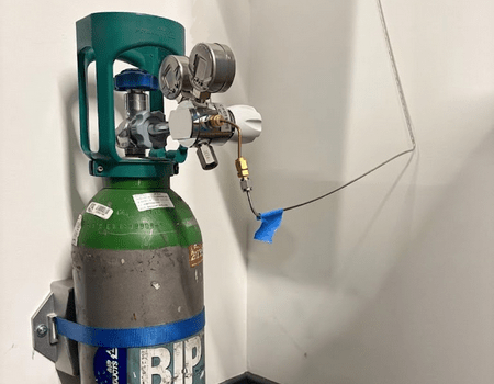
Before handling high-pressure gas equipment, ensure laboratory safety protocols are strictly met:
Secure Mounting: Always anchor high-pressure cylinders to a wall bracket or heavy-duty bench support using a safety chain or strap.
Environmental Safety: Keep cylinders away from direct heat sources, open flames, corrosive chemicals, and areas prone to mechanical impact.
Clear Access: Never place gas cylinders in high-traffic aisles or emergency evacuation routes. Restrict access to authorized personnel.
Step 2: Connecting the Pressure Regulator
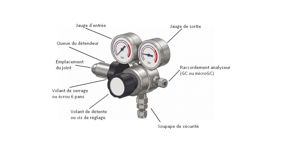
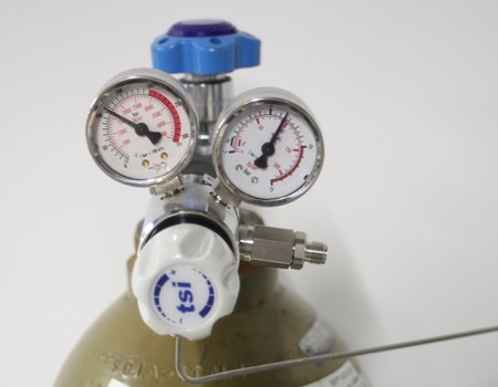
Inspection and Preparation Identification of pressure gauges, the clamping wheel and the location of the seal before connection.
Inspect Connections
Initial Knob Setting: Fully back out the pressure adjustment knob (counter-clockwise) until it turns freely, then turn it in clockwise approximately one full turn.Pro Tip: Pre-engaging the diaphragm mechanism prevents ambient air trapped within the regulator body from being back-flushed into the cylinder valve upon initial opening.
Alignment and Tightening Protocols – Depending on your gas standard specification, two main mounting types are encountered:
-
A. Handwheel Connection with Integrated O-Ring : Designed for tool-free manual connectionthis system presses the inlet nipple into the cylinder valve seat, relying on O-ring compression for gas-tight sealing.Inspect the O-ring for cracks, dirt, or deformation.Align the regulator along the valve outlet axis and tighten the handwheel firmly by hand only. Never use wrenches or pliers on handwheel fittings, as excessive torque will shear the O-ring or strip threads.
-
B. Hexagonal Nut Connection with Flat Sealing Washer : Used in high-torque configurations, this assembly requires a renewable flat gasket (washer) replaced at every cylinder change. Seat a new gasket into the face of the regulator inlet nipple.Thread the hex nut by hand for the first few turns to prevent cross-threading.Finalize tightening using a properly sized open-end wrench. Avoid over-torquing, which deforms or shears the flat gasket.
Critical Safety Identification: Threading Standards
Regulators are strictly categorized by gas compatibility to prevent accidental cross-connection:
-
Type C Regulators (Inert / Neutral Gases): Used for helium, argon, nitrogen and CO2. Features standard right-hand threads (tightens clockwise).
-
Type E Regulators (Flammable Gases): Used specifically for flammable gases (such as hydrogen or methane). Features left-hand threads (tightens counter-clockwise).
Visual Identification:
How do I identify a pressure regulator to the left at a glance? Type E nuts feature notched outer grooves cut into the hex faces. If you see these grooves, do not force the nut clockwise. Left-hand threading is a vital mechanical safeguard preventing combustible gas lines from connecting to inert supply networks.
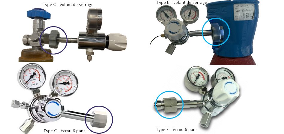
Visual identification of Type E pressure regulator for flammable gases (hexagonal split nut or specific steering wheel, surrounded in blue) against conventional Type C models (rounded in purple) for neutral gases.
⚠️ Essential Operational Hazards
Never stand directly in front of the regulator faceplate or pressure gauges when opening the main cylinder valve.
Never leave directly un tube libre connecté au détendeur. Une surpression accidentelle dans un tube non raccordé peut provoquer un effet « coup de fouet » très dangereux.
Step 3: Dual-Stage Regulator Purging (Step-by-Step)
Purging sweeps ambient air and humidity out of the fitting cavity created during cylinder changeover.
- Pressurize the Cavity Briefly open the main cylinder valve a quarter-turn, then close it immediately.
- The High-Pressure (HP) inlet gauge will jump to cylinder pressure (up to 200 bar / 2900 psi).
- The output gauge (BP) indicates the set pressure (up to 10 bar).
- Evacuate Air Open the regulator outlet valve slightly to release trapped gas. You will hear a brief hiss as the HP gauge pressure drops back toward zero while the cylinder valve remains closed.
- Repeat Cycles : Perform this press-and-bleed sequence 3 to 5 consecutive times to sweep air out of the inlet fitting.
- Set Working Pressure : Unscrew the regulator adjustment knob completely, then fully open the main cylinder valve.
-
- The HP gauge will display stable cylinder pressure.
- The BP gauge shall indicate 0 bar (closed adjustment rod).
Electronic Leak Testing
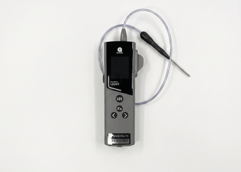
After purging, sweep an electronic leak detector across all threaded joints, face nuts, and compression fittings.
Detectable gases: H2, Helium, Argon.
Nitrogen (N2) Note: Electronic probes cannot easily detect N2 due to high atmospheric background levels. For N2, perform a pressure-drop test (hold system under pressure with cylinder valve closed for 15 minutes and monitor gauge drop).
Note by the Chemlys'expert: Leaks at the regulator are mainly due to defective joints or damaged threads. To guarantee you total safety, all the pressure regulators provided by Chemlys undergo an individual checked in the workshop before dispatch.
WARNING: Never use liquid bubble leak detectors (e.g., Snoop®) on analytical gas lines! Surfactant liquids leach into tubing via back-diffusion, permanently poisoning MEMS detectors, Micro GC injectors, and capillary column stationary phases. Always use an electronic leak detector.
Step 4: Connecting the Gas Analyzer
Selecting Tubing (1/8″ OD): Always use instrument-grade, pre-cleaned 1/8″ tubing. Ensure cuts are square and free of metal burrs or shavings.
The choice of material depends on the configuration of your laboratory:
-
316L Stainless Steel Tubing: Rigid, highly recommended for permanent laboratory setups. Cut cleanly using a dedicated roller tube cutter.
-
Copper Tubing: Flexible, suitable for mobile test carts. Coil excess length neatly to absorb vibration. It cuts with a pipe cutters. The excess length can be wound in turns to reduce congestion.
Compression Fitting Swagging (Swagelok / VICI)
- Cut the 1/8″ tube cleanly, ensuring the final 5 cm are perfectly straight..
- Slide components onto the tube in sequence: Nut, Back Ferrule, Front Ferrule, leaving 1 cm of exposed tubing at the end. (Note: Front and back ferrules may be separate, as with Swagelok®or integrated, as with VICI® fittings).).
- Insert the tube fully into the regulator LP outlet fitting until it seats firmly against the shoulder. Thread the nut by hand until finger-tight.
- Swagging/Tightening: Using two 7/16″ open-end wrenches (one backing wrench holding the fitting body, one turning the nut) tighten the nut 1/2 turn from finger-tight while holding the tube seated.
Caution: Over-tightening crushes the tubing ID and permanently damages fitting threads.
Under-Flow Connection Procedure
- Prepare analyzer-side tube end of the 1⁄8 tube (nut + counterferule + ferule).
- Adjust the regulator knob to establish a tiny purge flow (outlet pressure
Why this step? Making the final connection while gas is gently flowing sweeps away ambient air and particulates trapped inside the tube before it enters the analyzer manifold.. - Insert the tubing into the GC gas inlet fitting, hand-tighten the nut, and apply a 1/2 turn tightening with 7/16″ wrenches.
- The LP delivery gauge will register backpressure as the circuit seals.
- Service pressure adjustment: Adjust the final delivery pressure to instrument specifications
(e.g.: For MicroGC Fusion, the recommended pressure is 5.5 bar / 80 psi).
Step 5: Final Verification and Leak Troubleshooting
Once the circuit is under pressure, close the regulator valve: the inlet and outlet pressures must remain perfectly stable.
Complete the electronic leak check on all nuts and fittings.
What to do in case of a leak on the ferrules?
Incremental Tightening: If a micro-leak is detected, apply a slight additional turn (1/8 turn max) using backing wrenches until the leak stops.
Preventive replacement: If you feel abnormal thread resistance or galling, do not force the fitting. Replace the nut and ferrule set immediately to avoid galling the analyzer's internal inlet manifold.
Chemlys Expertise for Your Analytical Systems
A compromised carrier gas delivery system is the primary cause of baseline noise, ghost peaks, and detector downtime in GC and MicroGC analytical equipment.
As specialists in industrial gas analysis, Chemlys supports your laboratory with:
-
- Selection of high-precision pressure regulators and automated manifold panels.
- Supply of certified ultra-clean tubing, SilcoNert® treated lines, and Swagelok® / VICI® fittings.
- On-site commissioning, system qualification and analytical system maintenance.